
一,定义
An interrupt is usually defined as an event that alters the sequence of instructions executed by a processor.
Such events correspond to electrical signals generated by hardware circuits both inside and outside the CPU chip.
二,中断分类
• Synchronous interrupts — Exceptions
they are produced by the CPU control unit while executing instructions and are called synchronous because the control unit issues them only after terminating the execution of an instruction.
• Asynchronous interrupts — Interrupts
they are generated by other hardware devices at arbitrary times with respect to the CPU clock signals.
三,中断/异常来源及其分类
• Interrupts:
Interrupts are issued by interval timers and I/O devices.
Maskable interrupts
All IRQs issued by I/O devices(Interrupt ReQuests) give rise to maskable interrupts.
A maskable interrupt can be in two states: masked or unmasked;a masked interrupt is ignored by the control unit as long as it remains masked.
Nonmaskable interrupts
Only a few critical events (such as hardware failures) give rise to nonmaskable interrupts. Nonmaskable interrupts are always recognized by the CPU.
The nonmaskable interrupt (NMI) can be generated in either of two ways:
• External hardware asserts the NMI pin.
• The processor receives a message on the system bus (Pentium 4, Intel Core Duo, Intel Core 2, Intel Atom, and
Intel Xeon processors) or the APIC serial bus (P6 family and Pentium processors) with a delivery mode NMI.
When the processor receives a NMI from either of these sources, the processor handles it immediately by calling the NMI handler pointed to by interrupt vector number 2. The processor also invokes certain hardware conditions to ensure that no other interrupts, including NMI interrupts, are received until the NMI handler has completed executing (see Section 6.7.1, “Handling Multiple NMIs”).
Also, when an NMI is received from either of the above sources, it cannot be masked by the IF flag in the EFLAGS register.
It is possible to issue a maskable hardware interrupt (through the INTR pin) to vector 2 to invoke the NMI interrupt handler; however, this interrupt will not truly be an NMI interrupt. A true NMI interrupt that activates the processor’s NMI-handling hardware can only be delivered through one of the mechanisms listed above.
• Exceptions:
Exceptions are caused either by programming errors or by anomalous conditions that must be handled by the kernel.
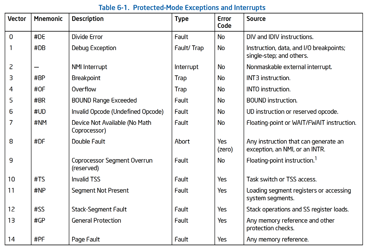
Processor-detected exceptions
Generated when the CPU detects an anomalous condition while executing an instruction. Depending on the value of the eip register that is saved on the Kernel Mode stack when the CPU control unit raises the exception,these are further divided into three groups:
Faults
Can generally be corrected; once corrected, the program is allowed to restart with no loss of continuity. The saved value of eip is the address of the instruction that caused the fault, and hence that instruction can be resumed when the exception handler terminates. Resuming the same instruction is necessary whenever the handler is able to correct the anomalous condition that caused the exception.
Traps
Reported immediately following the execution of the trapping instruction; after the kernel returns control to the program, it is allowed to continue its execution with no loss of continuity. The saved value of eip is the address of the instruction that should be executed after the one that caused the trap. A trap is triggered only when there is no need to reexecute the instruction that terminated. The main use of traps is for debugging purposes. The role of the interrupt signal in this case is to notify the debugger that a specific instruction has been executed (forinstance, a breakpoint has been reached within a program). Once theuser has examined the data provided by the debugger, she may ask that execution of the debugged program resume, starting from the next instruction.
Aborts
A serious error occurred; the control unit is in trouble, and it may be unable to store in the eip register the precise location of the instruction causing the exception. Aborts are used to report severe errors, such as hardware failures and invalid or inconsistent values in system tables.The interrupt signal sent by the control unit is an emergency signal used to switch control to the corresponding abort exception handler. This handler has no choice but to force the affected process to terminate.
Programmed exceptions
Occur at the request of the programmer. They are triggered by int or int3 instructions; the into (check for overflow) and bound (check on address bound) instructions also give rise to a programmed exception when the condition they are checking is not true. Programmed exceptions are handled by the control unit as traps; they are often called software interrupts. Such exceptions have two common uses: to implement system calls and to notify a debugger of a specific event .
四,SOURCES OF INTERRUPTS
The processor receives interrupts from two sources:
• External (hardware generated) interrupts.
External interrupts are received through pins on the processor or through the local APIC. The primary interrupt pins on Pentium 4, Intel Xeon, P6 family, and Pentium processors are the LINT[1:0] pins, which are connected to the local APIC (see Chapter 10, “Advanced Programmable Interrupt Controller (APIC)”). When the local APIC is
enabled, the LINT[1:0] pins can be programmed through the APIC’s local vector table (LVT) to be associated with any of the processor’s exception or interrupt vectors.
When the local APIC is global/hardware disabled, these pins are configured as INTR and NMI pins, respectively.
Asserting the INTR pin signals the processor that an external interrupt has occurred. The processor reads from the system bus the interrupt vector number provided by an external interrupt controller, such as an 8259A (see Section 6.2, “Exception and Interrupt Vectors”).
Asserting the NMI pin signals a non-maskable interrupt (NMI), which is assigned to interrupt vector 2.
• Software-generated interrupts.
The INT n instruction permits interrupts to be generated from within software by supplying an interrupt vector
number as an operand. For example, the INT 35 instruction forces an implicit call to the interrupt handler for interrupt 35.
Any of the interrupt vectors from 0 to 255 can be used as a parameter in this instruction. If the processor’s
predefined NMI vector is used, however, the response of the processor will not be the same as it would be from an NMI interrupt generated in the normal manner. If vector number 2 (the NMI vector) is used in this instruction, the NMI interrupt handler is called, but the processor’s NMI-handling hardware is not activated.
Interrupts generated in software with the INT n instruction cannot be masked by the IF flag in the EFLAGS register.
五,SOURCES OF EXCEPTIONS
The processor receives exceptions from three sources:
• Processor-detected program-error exceptions.
• Software-generated exceptions.
• Machine-check exceptions.
Program-Error Exceptions
The processor generates one or more exceptions when it detects program errors during the execution in an application program or the operating system or executive. Intel 64 and IA-32 architectures define a vector number for each processor-detectable exception. Exceptions are classified as faults, traps, and aborts (see Section 6.5, “Exception Classifications”).
Software-Generated Exceptions
The INTO, INT1, INT3, and BOUND instructions permit exceptions to be generated in software. These instructions allow checks for exception conditions to be performed at points in the instruction stream. For example, INT3 causes a breakpoint exception to be generated.
The INT n instruction can be used to emulate exceptions in software; but there is a limitation.1 If INT n provides a vector for one of the architecturally-defined exceptions, the processor generates an interrupt to the correct vector (to access the exception handler) but does not push an error code on the stack. This is true even if the associated hardware-generated exception normally produces an error code. The exception handler will still attempt to pop an error code from the stack while handling the exception. Because no error code was pushed, the handler will pop off and discard the EIP instead (in place of the missing error code). This sends the return to the wrong location.
Machine-Check Exceptions
The P6 family and Pentium processors provide both internal and external machine-check mechanisms for checking the operation of the internal chip hardware and bus transactions. These mechanisms are implementation dependent. When a machine-check error is detected, the processor signals a machine-check exception (vector 18) and returns an error code.
See Chapter 6, “Interrupt 18—Machine-Check Exception (#MC)” and Chapter 15, “Machine-Check Architecture,” for more information about the machine-check mechanism.
六,中断信号的产生/作用及处理方式
Each hardware device controller capable of issuing interrupt requests usually has a single output line designated as the Interrupt ReQuest (IRQ) line(More sophisticated devices use several IRQ lines.For instance, a PCI card can use up to four IRQ lines.). All existing IRQ lines are connected to the input pins of a hardware circuit called the Programmable Interrupt Controller, which performs the following actions:
1. Monitors the IRQ lines, checking for raised signals. If two or more IRQ lines are raised, selects the one having the lower pin number.
2. If a raised signal occurs on an IRQ line:
a. Converts the raised signal received into a corresponding vector.
b. Stores the vector in an Interrupt Controller I/O port, thus allowing the CPU to read it via the data bus.
c. Sends a raised signal to the processor INTR pin—that is, issues an interrupt.
d. Waits until the CPU acknowledges the interrupt signal by writing into one of the Programmable Interrupt Controllers (PIC) I/O ports; when this occurs,clears the INTR line.
3. Goes back to step 1.
The IRQ lines are sequentially numbered starting from 0; therefore, the first IRQ line is usually denoted as IRQ0. Intel’s default vector associated with IRQn is n+32. As mentioned before, the mapping between IRQs and vectors can be modified by issuing suitable I/O instructions to the Interrupt Controller ports.
Each IRQ line can be selectively disabled. Thus, the PIC can be programmed to disable IRQs. That is, the PIC can be told to stop issuing interrupts that refer to a given IRQ line, or to resume issuing them. Disabled interrupts are not lost; the PIC sends them to the CPU as soon as they are enabled again. This feature is used by most interrupt handlers, because it allows them to process IRQs of the same type serially.
Selective enabling/disabling of IRQs is not the same as global masking/unmasking of maskable interrupts. When the IF flag of the eflags register is clear, each maskable interrupt issued by the PIC is temporarily ignored by the CPU. The cli and sti assembly language instructions, respectively, clear and set that flag.
注:
enabling/disabling of IRQs:enable/disable一条或几条选中的线
masking/unmasking:所有的maskable interrupt

Traditional PICs are implemented by connecting “in cascade” two 8259A-style external chips. Each chip can handle up to eight different IRQ input lines. Because the INT output line of the slave PIC is connected to the IRQ2 pin of the master PIC, the number of available IRQ lines is limited to 15.
interrupt signals provide a way to divert the processor to code outside the normal flow of control. When an interrupt signal arrives, the CPU must stop what it’s currently doing and switch to a new activity; it does this by saving the current value of the program counter (i.e., the content of the eip and cs registers) in the Kernel Mode stack and by placing an address related to the interrupt type into the program counter.
But there is a key difference between interrupt handling and process switching: the code executed by an interrupt or by an exception handler is not a process. Rather, it is a kernel control path that runs at the expense of the same process that was running when the interrupt occurred . As a kernel control path, the interrupt handler is lighter than a process (it has less context and requires less time to set up or tear down).
Interrupt handling must satisfy the following constraints:
• Interrupts can come anytime, when the kernel may want to finish something else it was trying to do. The kernel’s goal is therefore to get the interrupt out of the way as soon as possible and defer as much processing as it can.
• Because interrupts can come anytime, the kernel might be handling one of them while another one (of a different type) occurs. This should be allowed as much as possible, because it keeps the I/O devices busy . As a result, the interrupt handlers must be coded so that the corresponding kernel control paths can be executed in a nested manner. When the last kernel control path terminates, the kernel must be able to resume execution of the interrupted process or switch to another process if the interrupt signal has caused a rescheduling activity.
• Although the kernel may accept a new interrupt signal while handling a previous one, some critical regions exist inside the kernel code where interrupts must be disabled. Such critical regions must be limited as much as possible because,according to the previous requirement, the kernel, and particularly the interrupt handlers, should run most of the time with the interrupts enabled.
七,APIC
The previous description refers to PICs designed for uniprocessor systems. If the system includes a single CPU, the output line of the master PIC can be connected in a straightforward way to the INTR pin of the CPU. However, if the system includes two or more CPUs, this approach is no longer valid and more sophisticated PICs are needed.
Being able to deliver interrupts to each CPU in the system is crucial for fully exploiting the parallelism of the SMP architecture. For that reason, Intel introduced starting with Pentium III a new component designated as the I/O Advanced Programmable Interrupt Controller (I/O APIC). This chip is the advanced version of the old 8259A Programmable Interrupt Controller; to support old operating systems, recent motherboards include both types of chip. Moreover, all current 80 × 86 microprocessors include a local APIC. Each local APIC has 32-bit registers, an internal clock; a local timer device; and two additional IRQ lines, LINT0 and LINT1, reserved for local APIC interrupts. All local APICs are connected to an external I/O APIC, giving rise to a multi-APIC system.
Figure 4-1 illustrates in a schematic way the structure of a multi-APIC system. An APIC bus connects the “frontend” I/O APIC to the local APICs. The IRQ lines coming from the devices are connected to the I/O APIC, which therefore acts as a routerwith respect to the local APICs. In the motherboards of the Pentium III and earlierprocessors, the APIC bus was a serial three-line bus; starting with the Pentium 4, the APIC bus is implemented by means of the system bus. However, because the APIC bus and its messages are invisible to software, we won’t give further details.
八,PROGRAM OR TASK RESTART
To allow the restarting of program or task following the handling of an exception or an interrupt, all exceptions
(except aborts) are guaranteed to report exceptions on an instruction boundary. All interrupts are guaranteed to be taken on an instruction boundary.
For fault-class exceptions, the return instruction pointer (saved when the processor generates an exception) points to the faulting instruction. So, when a program or task is restarted following the handling of a fault, the faulting instruction is restarted (re-executed). Restarting the faulting instruction is commonly used to handle exceptions that are generated when access to an operand is blocked. The most common example of this type of fault is a page�fault exception (#PF) that occurs when a program or task references an operand located on a page that is not in memory. When a page-fault exception occurs, the exception handler can load the page into memory and resume execution of the program or task by restarting the faulting instruction. To ensure that the restart is handled trans�parently to the currently executing program or task, the processor saves the necessary registers and stack pointers to allow a restart to the state prior to the execution of the faulting instruction.
For trap-class exceptions, the return instruction pointer points to the instruction following the trapping instruction. If a trap is detected during an instruction which transfers execution, the return instruction pointer reflects the transfer. For example, if a trap is detected while executing a JMP instruction, the return instruction pointer points to the destination of the JMP instruction, not to the next address past the JMP instruction. All trap exceptions allow program or task restart with no loss of continuity. For example, the overflow exception is a trap exception. Here, the return instruction pointer points to the instruction following the INTO instruction that tested EFLAGS.OF (overflow) flag. The trap handler for this exception resolves the overflow condition. Upon return from the trap handler, program or task execution continues at the instruction following the INTO instruction.
The abort-class exceptions do not support reliable restarting of the program or task. Abort handlers are designed to collect diagnostic information about the state of the processor when the abort exception occurred and then shut down the application and system as gracefully as possible.
Interrupts rigorously support restarting of interrupted programs and tasks without loss of continuity. The return
instruction pointer saved for an interrupt points to the next instruction to be executed at the instruction boundary where the processor took the interrupt. If the instruction just executed has a repeat prefix, the interrupt is taken at the end of the current iteration with the registers set to execute the next iteration.
The ability of a P6 family processor to speculatively execute instructions does not affect the taking of interrupts by the processor. Interrupts are taken at instruction boundaries located during the retirement phase of instruction execution; so they are always taken in the “in-order” instruction stream. See Chapter 2, “Intel® 64 and IA-32 Architectures,” in the Intel® 64 and IA-32 Architectures Software Developer’s Manual, Volume 1, for more information about the P6 family processors’ microarchitecture and its support for out-of-order instruction execution.
Note that the Pentium processor and earlier IA-32 processors also perform varying amounts of prefetching and
preliminary decoding. With these processors as well, exceptions and interrupts are not signaled until actual “in order” execution of the instructions. For a given code sample, the signaling of exceptions occurs uniformly when the code is executed on any family of IA-32 processors (except where new exceptions or new opcodes have been defined).
九,Handling Multiple NMIs
While an NMI interrupt handler is executing, the processor blocks delivery of subsequent NMIs until the next execution of the IRET instruction. This blocking of NMIs prevents nested execution of the NMI handler. It is recommended that the NMI interrupt handler be accessed through an interrupt gate to disable maskable hardware interrupts (see Section 6.8.1, “Masking Maskable Hardware Interrupts”).
An execution of the IRET instruction unblocks NMIs even if the instruction causes a fault. For example, if the IRET instruction executes with EFLAGS.VM = 1 and IOPL of less than 3, a general-protection exception is generated (see Section 20.2.7, “Sensitive Instructions”). In such a case, NMIs are unmasked before the exception handler is invoked.
10,ENABLING AND DISABLING INTERRUPTS
The processor inhibits the generation of some interrupts, depending on the state of the processor and of the IF and RF flags in the EFLAGS register, as described in the following sections.
Masking Maskable Hardware Interrupts
The IF flag can disable the servicing of maskable hardware interrupts received on the processor’s INTR pin or
through the local APIC (see Section 6.3.2, “Maskable Hardware Interrupts”). When the IF flag is clear, the
processor inhibits interrupts delivered to the INTR pin or through the local APIC from generating an internal interrupt request; when the IF flag is set, interrupts delivered to the INTR or through the local APIC pin are processed as normal external interrupts.
The IF flag does not affect non-maskable interrupts (NMIs) delivered to the NMI pin or delivery mode NMI
messages delivered through the local APIC, nor does it affect processor generated exceptions. As with the other flags in the EFLAGS register, the processor clears the IF flag in response to a hardware reset.
The fact that the group of maskable hardware interrupts includes the reserved interrupt and exception vectors 0 through 32 can potentially cause confusion. Architecturally, when the IF flag is set, an interrupt for any of the
vectors from 0 through 32 can be delivered to the processor through the INTR pin and any of the vectors from 16 through 32 can be delivered through the local APIC. The processor will then generate an interrupt and call the interrupt or exception handler pointed to by the vector number. So for example, it is possible to invoke the page�fault handler through the INTR pin (by means of vector 14); however, this is not a true page-fault exception. It is an interrupt. As with the INT n instruction (see Section 6.4.2, “Software-Generated Exceptions”), when an interrupt is generated through the INTR pin to an exception vector, the processor does not push an error code on the stack, so the exception handler may not operate correctly.
The IF flag can be set or cleared with the STI (set interrupt-enable flag) and CLI (clear interrupt-enable flag)
instructions, respectively. These instructions may be executed only if the CPL is equal to or less than the IOPL. A general-protection exception (#GP) is generated if they are executed when the CPL is greater than the IOPL.1 If IF = 0, maskable hardware interrupts remain inhibited on the instruction boundary following an execution of STI.2
The inhibition ends after delivery of another event (e.g., exception) or the execution of the next instruction.
The IF flag is also affected by the following operations:
• The PUSHF instruction stores all flags on the stack, where they can be examined and modified. The POPF
instruction can be used to load the modified flags back into the EFLAGS register.
• Task switches and the POPF and IRET instructions load the EFLAGS register; therefore, they can be used to
modify the setting of the IF flag.
• When an interrupt is handled through an interrupt gate, the IF flag is automatically cleared, which disables
maskable hardware interrupts. (If an interrupt is handled through a trap gate, the IF flag is not cleared.)
See the descriptions of the CLI, STI, PUSHF, POPF, and IRET instructions in Chapter 3, “Instruction Set Reference, A-L,” in the Intel® 64 and IA-32 Architectures Software Developer’s Manual, Volume 2A, and Chapter 4, “Instruction Set Reference, M-U,” in the Intel® 64 and IA-32 Architectures Software Developer’s Manual, Volume 2B, for a detailed description of the operations these instructions are allowed to perform on the IF flag.
Masking Instruction Breakpoints
The RF (resume) flag in the EFLAGS register controls the response of the processor to instruction-breakpoint conditions (see the description of the RF flag in Section 2.3, “System Flags and Fields in the EFLAGS Register”). When set, it prevents an instruction breakpoint from generating a debug exception (#DB); when clear, instruction breakpoints will generate debug exceptions. The primary function of the RF flag is to prevent the processor from going into a debug exception loop on an instruction-breakpoint. See Section 17.3.1.1, “Instruction-Breakpoint Exception Condition,” for more information on the use of this flag.
As noted in Section 6.8.3, execution of the MOV or POP instruction to load the SS register suppresses any instruction breakpoint on the next instruction (just as if EFLAGS.RF were 1).
Masking Exceptions and Interrupts When Switching Stacks
To switch to a different stack segment, software often uses a pair of instructions, for example:
MOV SS, AX
MOV ESP, StackTop
(Software might also use the POP instruction to load SS and ESP.)
If an interrupt or exception occurs after the new SS segment descriptor has been loaded but before the ESP register has been loaded, these two parts of the logical address into the stack space are inconsistent for the duration of the interrupt or exception handler (assuming that delivery of the interrupt or exception does not itself load a new stack pointer).
To account for this situation, the processor prevents certain events from being delivered after execution of a MOV to SS instruction or a POP to SS instruction. The following items provide details:
• Any instruction breakpoint on the next instruction is suppressed (as if EFLAGS.RF were 1).
• Any data breakpoint on the MOV to SS instruction or POP to SS instruction is inhibited until the instruction
boundary following the next instruction.
• Any single-step trap that would be delivered following the MOV to SS instruction or POP to SS instruction
(because EFLAGS.TF is 1) is suppressed.
• The suppression and inhibition ends after delivery of an exception or the execution of the next instruction.
• If a sequence of consecutive instructions each loads the SS register (using MOV or POP), only the first is
guaranteed to inhibit or suppress events in this way.
Intel recommends that software use the LSS instruction to load the SS register and ESP together. The problem
identified earlier does not apply to LSS, and the LSS instruction does not inhibit events as detailed above.
11,PRIORITIZATION OF CONCURRENT EVENTS
If more than one event is pending at an instruction boundary (between execution of instructions), the processor
services them in a predictable order. Table 6-2 shows the priority among classes of event sources.
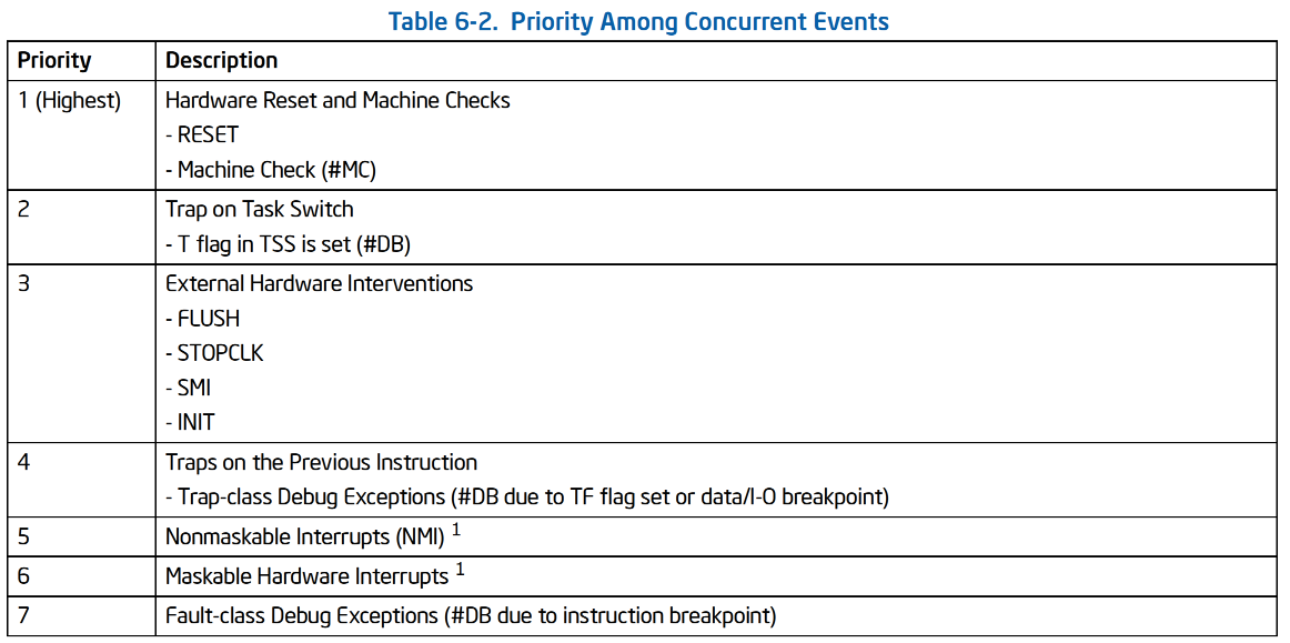
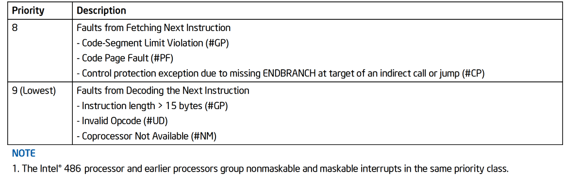
The processor first services a pending event from the class which has the highest priority, transferring execution to the first instruction of the handler. Lower priority exceptions are discarded; lower priority interrupts are held pending. Discarded exceptions may be re-generated when the event handler returns execution to the point in the program or task where the original event occurred. While the priority among the classes listed in Table 6-2 is consistent across processor implementations, the priority of events within a class is implementation-dependent and may vary from processor to processor.
Table 6-2 specifies the prioritization of events that may be pending at an instruction boundary. It does not specify the prioritization of faults that arise during instruction execution or event delivery (these include #BR, #TS, #NP, #SS, #GP, #PF, #AC, #MF, #XM, #VE, or #CP). It also does not apply to the events generated by the “Call to Interrupt Procedure” instructions (INT n, INTO, INT3, and INT1), as these events are integral to the execution of those instructions and do not occur between instructions.
原文地址:http://www.cnblogs.com/xiangsplayground/p/16852030.html
1. 本站所有资源来源于用户上传和网络,如有侵权请邮件联系站长!
2. 分享目的仅供大家学习和交流,请务用于商业用途!
3. 如果你也有好源码或者教程,可以到用户中心发布,分享有积分奖励和额外收入!
4. 本站提供的源码、模板、插件等等其他资源,都不包含技术服务请大家谅解!
5. 如有链接无法下载、失效或广告,请联系管理员处理!
6. 本站资源售价只是赞助,收取费用仅维持本站的日常运营所需!
7. 如遇到加密压缩包,默认解压密码为"gltf",如遇到无法解压的请联系管理员!
8. 因为资源和程序源码均为可复制品,所以不支持任何理由的退款兑现,请斟酌后支付下载
声明:如果标题没有注明"已测试"或者"测试可用"等字样的资源源码均未经过站长测试.特别注意没有标注的源码不保证任何可用性